Neopad
Recently I dove (again) into the world of the mechanical keyboard, but this time with a budget higher than zero LOL
I already have a couple of mechs: a full-size Logitech with ISO layout (cause I'm Italian) it's my main keyboard and a 60% Anne Pro 2 with ANSI layout that I use only for coding. Somebody will be satisfied with those, but if you are into this hobby you know very well that there will never be "enough keyboards" ;)
After searching for a nice deal around the net, I stumbled across this GitHub page where are listed all the main DIY mechanical keyboards. A lot of them have open-source Gerber files and firmware code. I fall into this pit and, as soon I realized that prototype a PCB in low quantity was just a few dollars plus shipping, I decided to design my own keeb!
I downloaded KiCad, I downloaded KiCad, a free and open-source EDA for PCB design. Look a couple of tutorials, and found this incredibly detailed guide specifically for design mechanical keyboard PCBs.
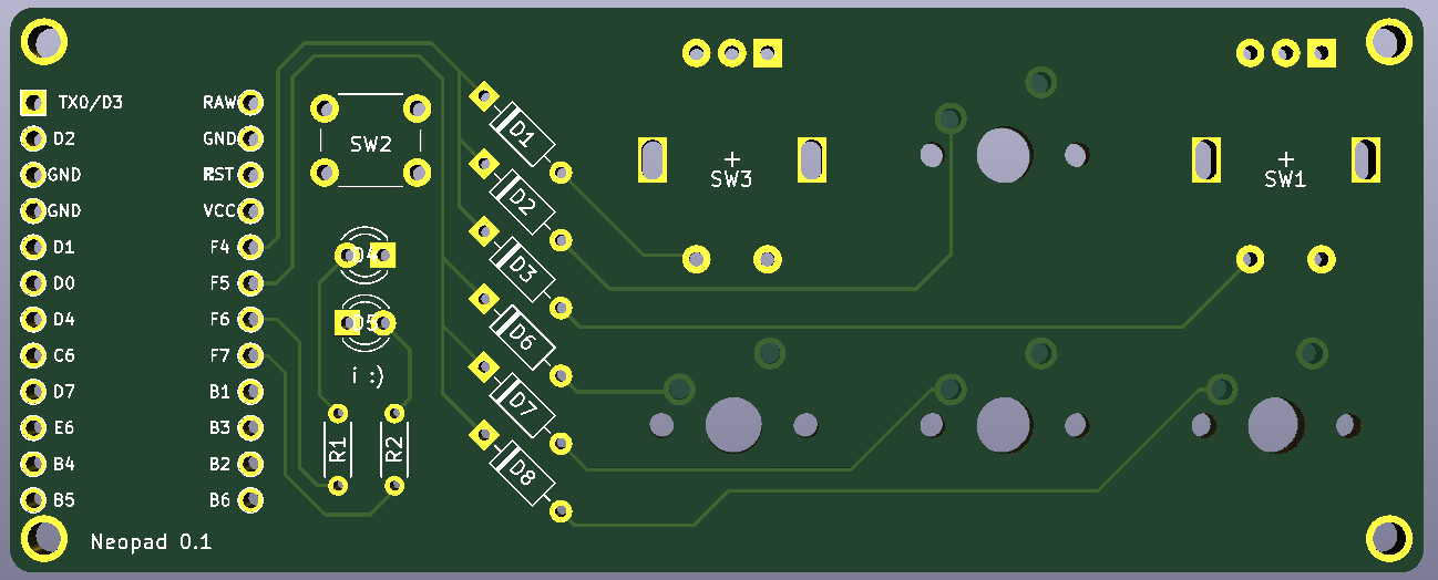
After this tutorial, I realized that maybe a full keeb was too much for the first experiment, so I decided to stay humble and start with a macropad. I give myself just one weekend to design and order all the components. This was necessary because I didn't want to spend hours on little details like graphics or OCD vias placing. This was the (very raw) design I came with:
After 2/3 weeks all the components and PCB arrived. Time to build!
I was very pleased to discover that almost everything was good. The only exceptions were:
- Resistors were a little too long for the holes I made so I had to bend the pins under the body;
- The Pro Micro clone wasn't the same size as the standard one (and has a mini USB), I ordered ASAP a substitute.
The day after I received the right Pro Micro clone, now I was ready to start soldering. Everything went well (unexpectedly, because I still haven't soldered often in my life).
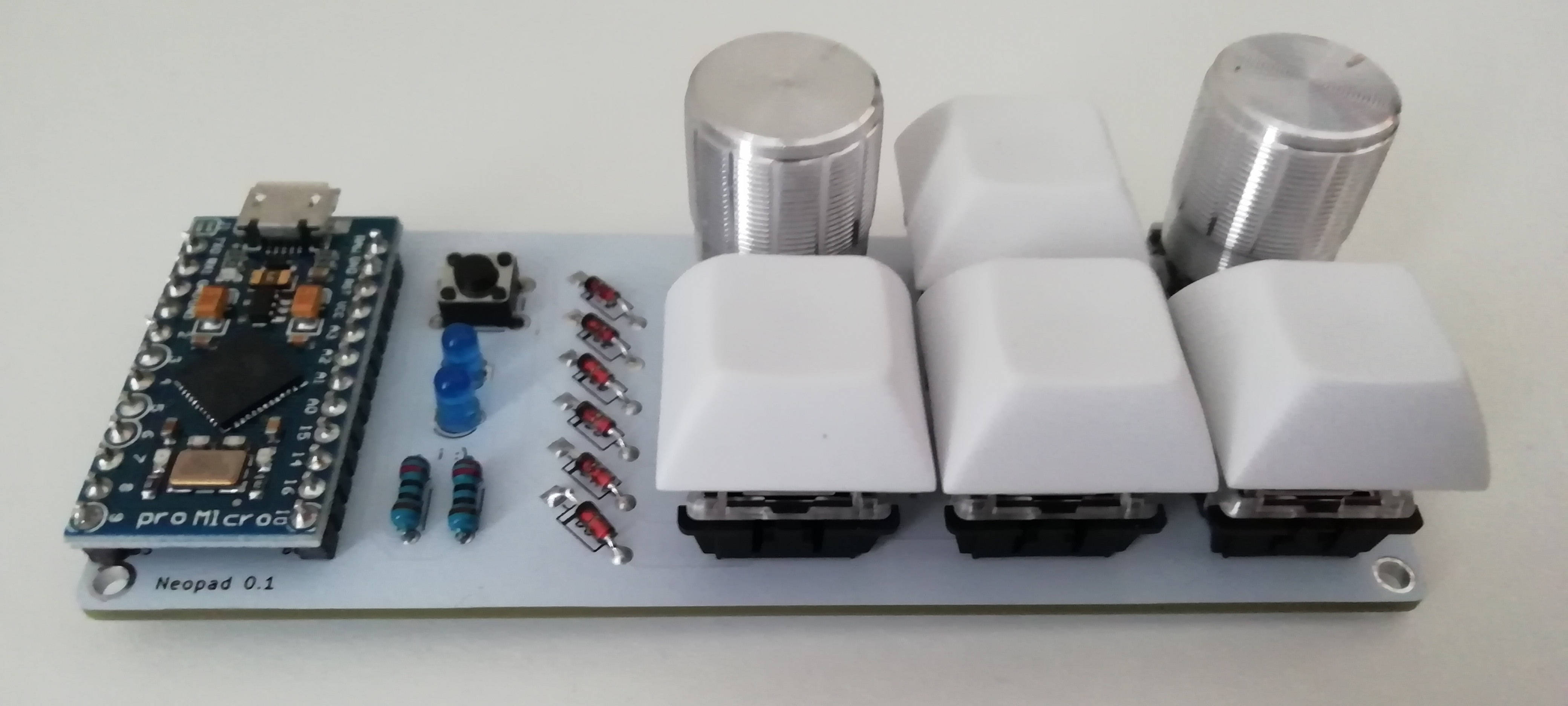
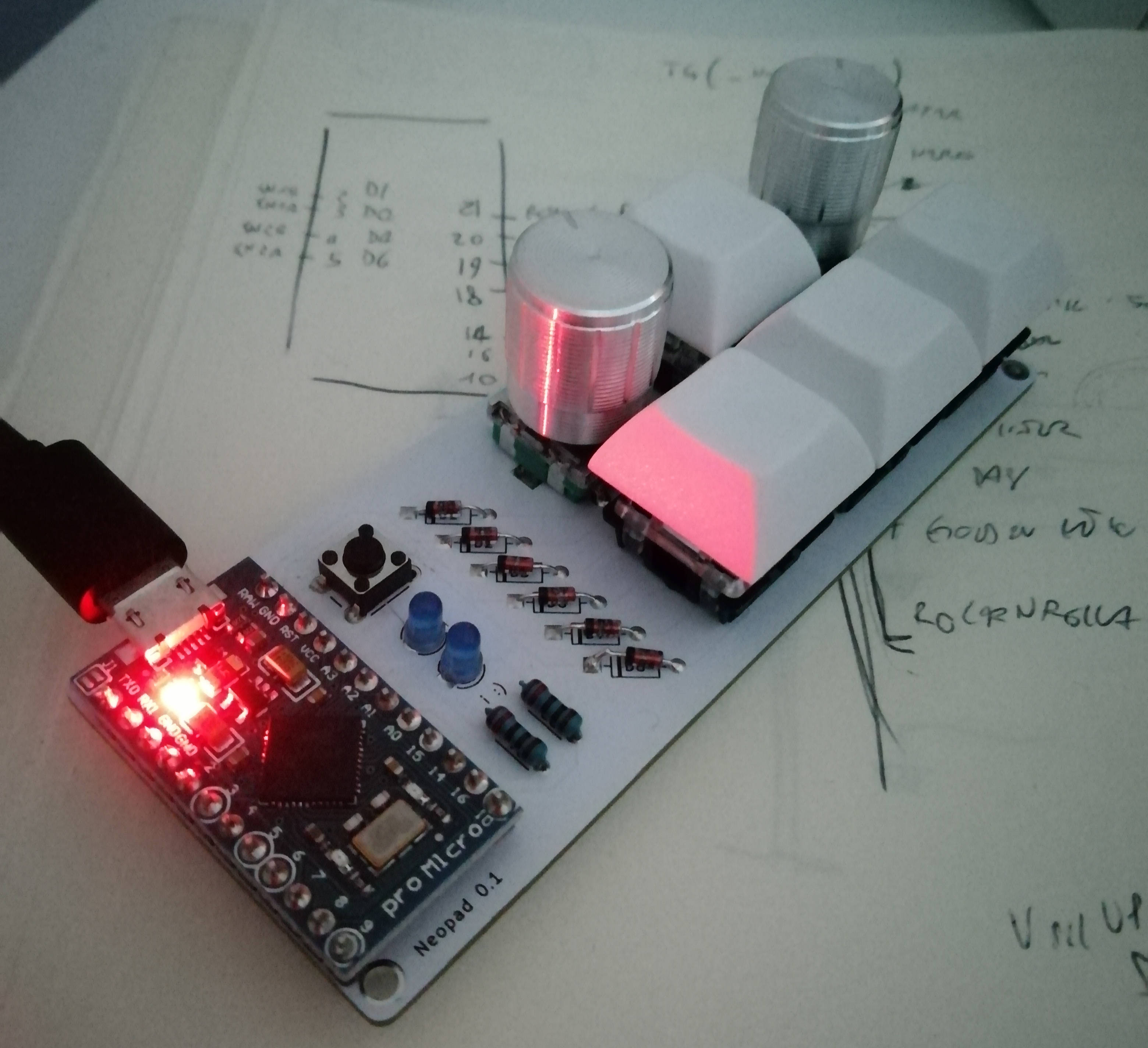
But for some reason, when I connected the macropad to the PC, it didn't detect it and a red led on the controller was on...
After a long headache, I found out that the pins that I used under the reset button was internally connected, so it acts like it was always pressed. I should have chosen two pins in different rows.
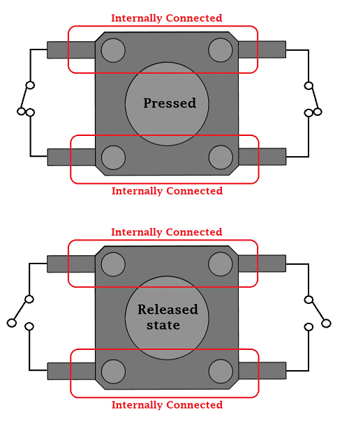
I bought a desolder pump and after a lot of *****, I desoldered the button and placed a new one with broken pins (A) to the ground (to avoid undesired behavior like the previous one) and the correct normally closed pin (B) connected to the GND pin (C) on the controller. And... it works!
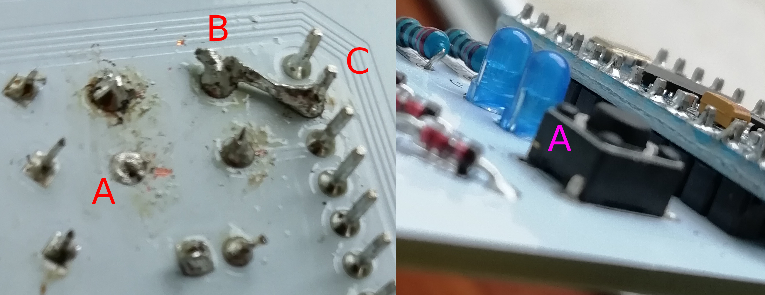
But it was too soon to celebrate because it was there that I discovered that the firmware side was not so easy as I expected. Long story short: I had the QMK development env set up following these videos, found and duplicate the imchipwood's dumbpad code which had luckily similar components to the Neopad, and I started file by file to edit it to my purpose.
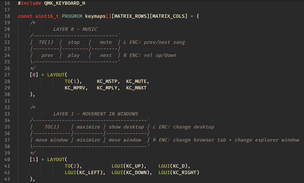
In the end, after a whole Sunday of coding, I made it!
Update: after a week I build a case with biscuits cardboard (because I didn't know what to use to make a prettier one) and posted this on Reddit. It was my most upvoted post of all time! So many comments and good suggestions for the case upgrade. Thanks, guys <3
Update 2: I decided to revision the PCB design before publishing the Gerber and the code so everybody can learn what I had learnt from somebody before me. This was a very satisfying project and I can't wait to make a full keyboard!